Access Control Design on KL46Z
A compact access-control unit based on KL46Z.
I built a compact access-control unit around the NXP FRDM-KL46Z (MKL46Z256VLL4). It takes passwords from a 3×4 matrix keypad, shows immediate feedback on a 4-digit segmented LCD (SLCD), and actuates a door strike through a relay driver. Users and administrators follow separate workflows, and credentials are stored in on-chip Flash so the device remains functional after resets or power loss. The more important goal, however, was not the feature list—it was to make the system behave like a deployable device: predictable interaction, safe defaults, and resilience designed into the hardware rather than “patched” in firmware.
Workflow as a contract, not just a diagram
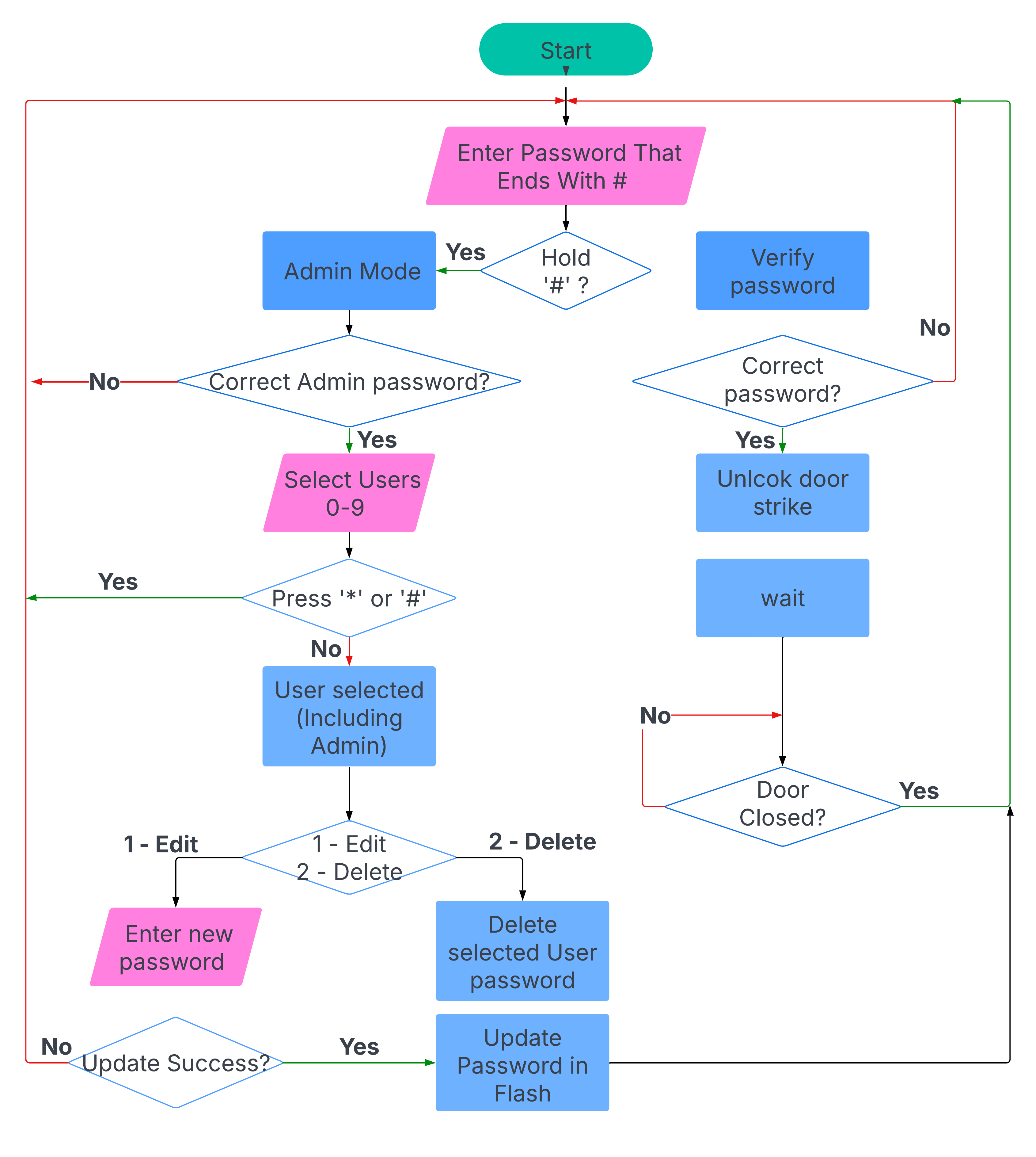
In embedded projects, the fastest way to create bugs is to treat the workflow as something you “explain afterwards.” I used the workflow as a behavioural contract and tried to keep the firmware honest to it. Password entry is explicitly terminated by ‘#’, so the user never wonders whether the device is still listening, and the device never has to guess when the input ends. Admin mode is deliberately harder to enter: a “hold ‘#’” gesture prevents accidental entry, and an admin password gate prevents destructive operations from being triggered by casual keypad use. Once inside admin mode, the actions are intentionally limited to what is operationally meaningful on a minimal UI: select a user slot, then edit or delete.
This structure matters because the interface is constrained. With only a keypad and a 4-digit display, ambiguity becomes visible immediately. The constraint is a design tool: it forces the interaction to be deterministic and pushes complexity away from the user and into a state machine that can be tested.
Hardware: designing for power events and physical boundaries
Most “it works on the bench” prototypes quietly assume stable power and forgiving loads. A door controller is the opposite: it sits on a wall, experiences interruptions, and interfaces with inductive hardware. The hardware therefore had to be a resilience layer, not just a carrier for the MCU.
The schematic was organised into functional blocks—power supply, USB interface, LCD mapping, keypad header, crystal oscillator, relay control, and MCU core—so each boundary can be reasoned about independently. That separation was not just for readability; it was a way to force myself to ask the right questions per block. Where does noise enter? What fails first? What happens on partial power? If a fault occurs, does the system fail closed?
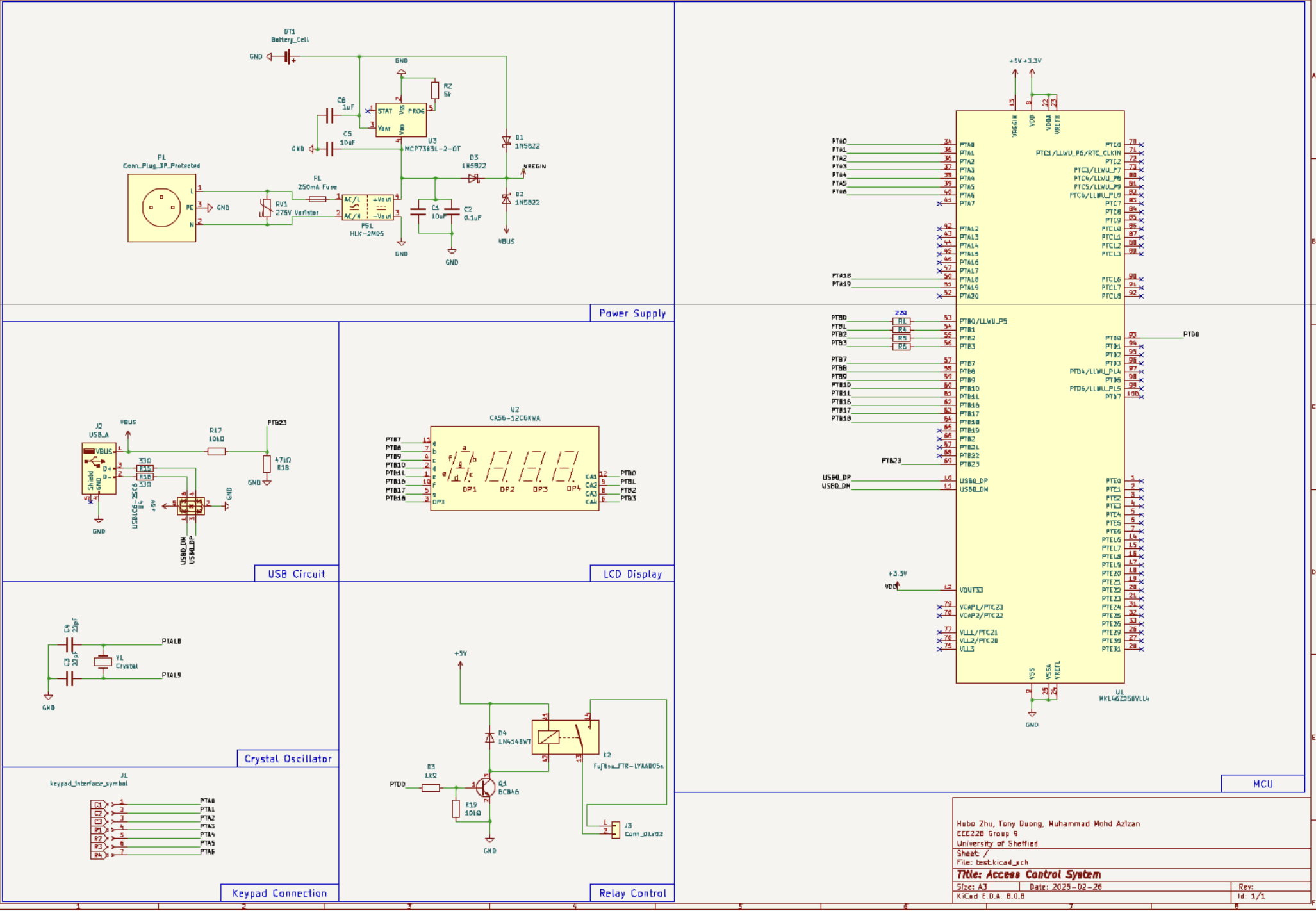
Power architecture: I learned to distrust “software-managed resilience”
Power ended up being the most instructive part of the build. The common temptation is to detect outages in firmware and then “switch to battery.” The problem is that the MCU is least trustworthy exactly when you need it to act—during a supply collapse and potential brownout. I therefore chose a hardware-defined source selection path (diode OR-ing) so AC-derived 5 V, USB 5 V, and a Li-ion backup path can coexist and the board naturally runs from the highest available source. Charging is handled by a dedicated IC so the battery remains ready without requiring any application-level control.
This is deliberately conservative. It is not the most efficiency-optimised solution, but it avoids subtle timing assumptions and reduces the risk of oscillating brownouts or undefined intermediate states. In other words, it makes power behaviour boring and predictable—which is exactly what firmware wants.
Keypad and LCD: minimal UI forces high signal-to-noise decisions
The keypad interface is a classic embedded reliability trap. Without disciplined scanning and debounce, the system either misses presses or double-counts them, and users blame the device rather than the code. Here the hardware is simple (a matrix keypad header) and the reliability comes from the firmware producing stable key events. The LCD mapping uses the KL46Z SLCD capability so the CPU does not need to bit-bang segments. With only four digits, the display strategy must be restrained: show the most recent digits during entry, and keep prompts short and consistent rather than trying to “explain everything” on-screen.
Relay driver: actuation is a safety boundary
Unlocking is not just another GPIO toggle; it is a physical action that must be explicit, bounded, and electrically well-behaved. The relay is driven via a transistor stage sized for saturation, with a flyback diode to clamp inductive transients. The goal is not only to switch the load reliably, but also to ensure that switching does not inject disturbances into the logic supply that could cause resets or undefined states. A subtle but important mindset shift here is treating the relay path as part of system integrity: if actuation destabilises the MCU, then “unlock” becomes a denial-of-service vector and a debugging nightmare.
PCB: when the design becomes real
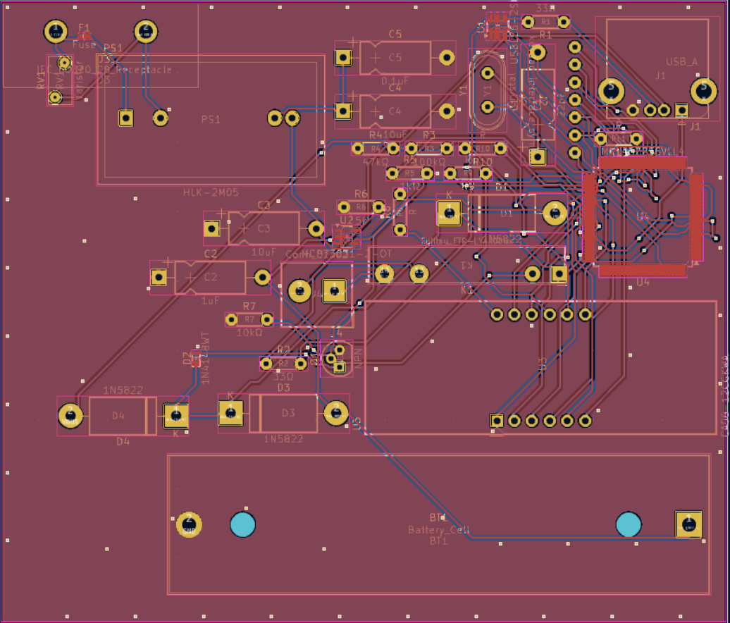
A schematic that works is not yet a board that behaves. The PCB layout forces you to confront what matters physically: where current actually flows, how return paths behave, how connectors will be used, and how much “engineering intent” survives the move from a tidy diagram to copper.
I tried to keep the layout aligned with the functional boundaries: power and high-current paths are compact, the MCU and decoupling are treated as the stability core, and headers are placed so wiring is straightforward in an enclosure. Even on a small two-layer board, these decisions dominate robustness far more than any single clever circuit trick. The layout also makes it easier to reason about failures: when something goes wrong, you can localise it to a block instead of hunting across an entangled board.
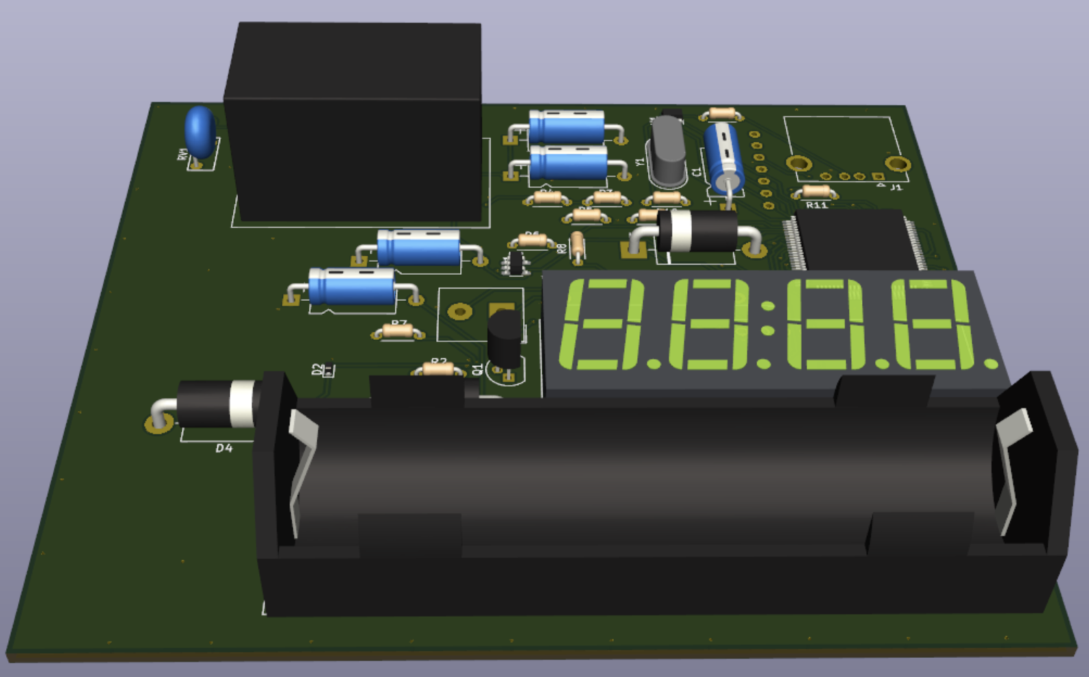
3D sanity check: the hidden part of “deployable”
The 3D render is not an aesthetic add-on; it is an engineering tool. It catches problems that are expensive to discover late: connector clearance, component height conflicts, and the practical alignment between the display, keypad cable, and enclosure openings. This is the stage where the project stops being an electronics exercise and starts resembling a small product. If the board cannot be assembled cleanly, mounted reliably, and connected without strain, then it is not deployable no matter how correct the firmware is.
Persistence: Flash is not a database, so treat it like a failure surface
Storing credentials in Flash sounds simple until you consider partial writes. Power can fail mid-update, and Flash does not provide transactional semantics by default. The key design choice was to validate stored data before trusting it and to prefer safe rejection over optimistic acceptance. For access control, false negatives are annoying; false positives are unacceptable. That asymmetry shapes the storage logic and reinforces the broader theme: when uncertain, fail closed.
What I would improve next (and why)
If I iterate a second revision, I would start with boundary hardening rather than new features. Electrically, I would strengthen safety separation around the mains-derived supply and improve manufacturability with clearer test points and bring-up hooks. System-wise, I would formalise a low-power story so that battery-backed operation is not just “it stays on,” but “it stays on predictably for a quantified duration.” These are not headline-grabbing changes, but they are exactly what turns a working prototype into something trustworthy in day-to-day use.
Code
Source code are available here: https://github.com/0xCapy/DoorAccessControl