AccessControl System Based On KL46Z
Categories MCU System
Tags Microcontroller
Building a KL46Z-Based Access Control System
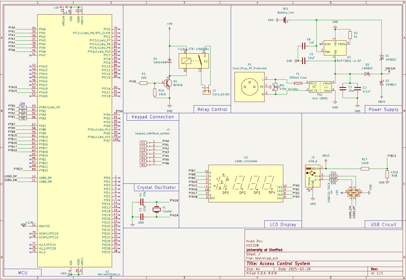
In this post, I’ll walk you through setting up a door access control system using an MKL46Z256 microcontroller. The schematic below illustrates the hardware design, including the LCD display, keypad interface, relay output, and more.
Overview of the System
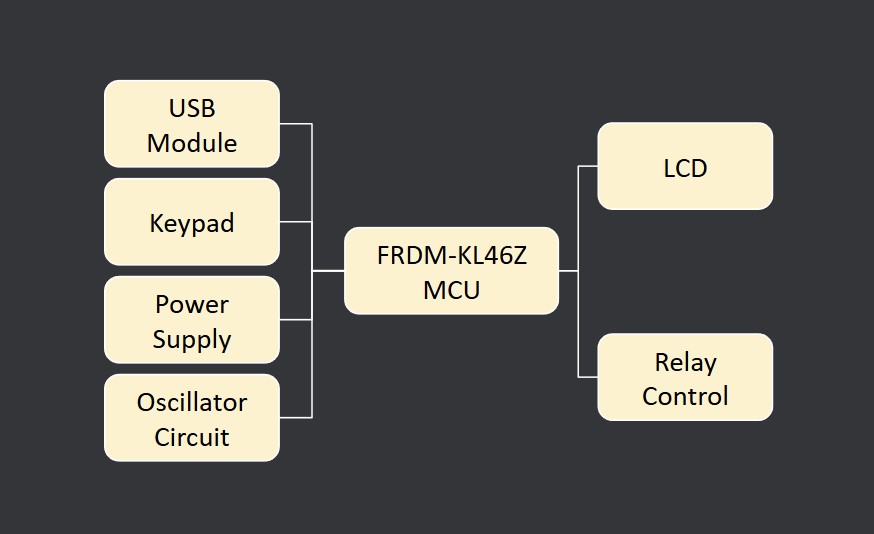
- Microcontroller (MKL46Z256): Handles the system logic—reading keypad input, driving the LCD, and controlling the relay.
- Power Supply Circuit: Ensures the microcontroller and peripherals get stable voltage. Includes an optional backup battery if you want the system to keep running briefly during power outages.
- Keypad Connection: Allows users to enter access codes.
- LCD Display: Provides feedback to the user (e.g., prompts to enter a code, success/failure messages).
- Relay Control: Drives a relay to lock/unlock a door strike.
- USB Circuit: Facilitates programming and debugging over USB (via the FRDM-KL46Z or a similar development board).
Step-by-Step Hardware Assembly
Gather Components
- KL46Z development board (or your own custom PCB following the schematic).
- Keypad (3x4 or 4x4) for code entry.
- 5V power supply (with appropriate regulation for 3.3V, if not already on the dev board).
- Relay module rated for your door strike voltage and current.
- LCD or segmented display (optional but recommended for user feedback).
- Wires, jumpers, and a breadboard (if prototyping).
Pro Tip:
Use well-labeled wiring harnesses or a breakout board to avoid confusion when hooking up the keypad pins.Connect the KL46Z Board
- Power Lines: Connect the board’s 3.3V and GND to the correct rails on the breadboard or your PCB.
- Keypad Pins: Wire each row and column pin to the matching GPIO pins defined in your software.
- LCD Pins (if used): Match the segment pins (LCD_Pxx) or use the dev board’s on-board LCD if available.
- Relay Driver: Use a transistor or MOSFET and a diode (as shown in the schematic) to switch the relay coil.
- USB Connectivity: Attach a USB cable to the “OpenSDA” port (if using an FRDM board) for programming and debugging.
My Experience:
I found it helpful to label each wire on both ends, especially for the keypad and LCD segments, to avoid swapping rows/columns.Software Setup and Programming
3.1 Installing Required Tools
- ARM Mbed Studio or another compatible IDE.
- ARM Mbed OS library loaded in your project.
- Clone The Repo https://github.com/0xCapy/DoorAccessControl.git
- The work flow of it is shown below
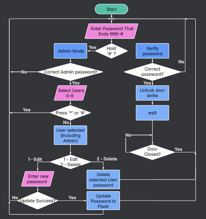
Writing the Firmware
- Initialize Peripherals:
Configure the GPIO pins for the keypad as inputs (with pull-ups) and the relay as an output. - LCD Setup (Optional):
Initialize the on-board or external LCD driver if present. - Main Loop:
- Read keypad input.
- Validate access codes.
- Update LCD messages.
- Toggle relay if the code is correct or if a supervisor command is entered.
Pro Tip:
Use interrupt-driven or RTOS-based tasks to keep the system responsive, especially if you need to poll the keypad or drive a display in parallel.Flash and Test
- Connect USB from your PC to the FRDM-KL46Z board.
- Compile & Download your .bin file using Mbed Studio or the
mbed-cli. - Open a Serial Monitor (e.g., in Mbed Studio) to read any debug
printf()statements.
Testing and Validation
- Power On the system and confirm the microcontroller boots properly (LED indicators or debug output).
- Enter a Test Code on the keypad. Check that the LCD updates or that debug prints appear on serial.
- Relay Activation: Use a simple code (like “1234”) and verify the relay coil energizes or the door strike toggles.
- Supervisor Mode: If you implemented a higher-level access code, confirm you can change the default code.
My Experience:
During my testing, the biggest issues came from misreading the keypad wiring. Double-check row and column configurations before concluding your firmware is at fault.Tips
- Label Everything: Reduces wiring confusion and speeds up debugging.
- Use a Dev Board First: Easier to isolate problems and test new ideas before committing to a custom PCB.
- Incremental Testing: Validate small sections (keypad, LCD, relay) independently before combining them.
- Power Budget: If you need standby operation during power outages, calculate battery capacity requirements ahead of time.